 A new CADSIM Plus multi-document interface will be introduced with version 3.0. The purpose of the new interface is to allow two or more CADSIM Plus drawings to be developed as separate simulations, and then linked together to run as a single simulation model.
The new multi-document interface features tabbed windows, one for each drawing, that are available in both drawing and simulation modes.
One of the advantages of this approach to modelling, is that it allows you to run each drawing to a steady-state and save a startup file, prior to running them as a group. If done properly, this can save a lot of time in getting a large simulation to run in a stable condition.
Another advantage, is that more than one engineer can collaborate by working on their part of the simulation, and then combine their work together. It also makes it easier to make followup changes, avoiding the necessity of passing the entire simulation from person to person. It makes it easier to plot individual drawings and to debug specification problems.
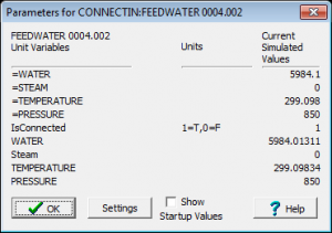
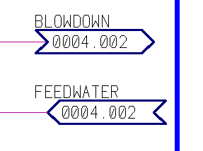
Connections between drawings are made using new ConnectIn and ConnectOut units. The Connect units bridge the gap between drawings.
Connections can be drawn in a form which is similar to P&C or P&ID style stream continuity symbols. CADSIM Plus v3.0 will include a set of drawing parts configured for visible and invisible connections in several orientations.
Each drawing is assigned a unique drawing name identifier that is stored as part of the drawing options. Connect units use the drawing name, along with unique polygon names in the form of stream identifiers, to establish connections.
If a drawing is run by itself, its ConnectIn units act as stream sources and use special unit specifications to supply a set values to initialize the simuation to run. These initial values are supplied by the user. Later, these values can be replaced by better calculated values when the drawings are run as a set and startup files are created. These values are given a ‘=’ prefix.
Connect units can also be used as interchanges between drawings that have different process chemistries and units of measure. This allows a set of drawings to use up to nine process stream definitions per drawing.
Connect units will also automatically convert units of measure between streams on different drawings. Connect units can also be used to extend flow and pressure flow networks between drawings.
 A typical workflow involves creating one or more process drawings of specific areas of the process. The internal drawing number is set for each and connect units are placed on each stream that is continued to or from another drawing. ConnectIn units are then specified with set values by the user.
When two or more drawings are completed, their names are entered into a text file which is given a .draproj file name extension. This project configuration may also include other information about each drawing, such as its time step.
When CADSIM Plus opens a [filename].draproj, it automatically reads each of the drawing files that it contains and then loads each of the drawings into a separate, tabbed window. You can then run the drawings as a set, tune controllers and save a set of startup files, one for each drawing, as well as update the saved values for ConnectIn units.
CADSIM Plus v3.0 will ship with sample drawings set up as a multi-document project. The drawings contain examples of visible and invisible Connect units on minor and major process streams. Each of these sample drawings can also be run by itself with no modification.

